I got my start in the radio hobby listening to a Japanese 8-transistor radio that my aunt bought me for Christmas in 1962 or so. Up to that time I don't think that I had ever even tuned a radio. We had an AC/DC metal-cased deathtrap AA5 in our kitchen, but I was discouraged from messing with it. In those days you were liable to hear some pretty odd things on AM radio at night, and of course the magical things that happened to make those distant stations heard made a lasting impression.
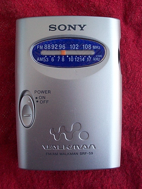
Even as I moved on to ham radio I kept an interest in listening for DX on the AM band, and I always had a little portable radio that I would often listen to in bed before going to sleep. Some years back, I had a Sony Walkman-type AM/FM radio, and it died, so I replaced it with a new Sony SRF-59. The radio worked OK on FM, but it was pretty deaf on AM. Quite a disappointment, but I lived with it for a few years until the tuning capacitor started making noise. I threw it in the junk pile and looked around for a new replacement, but Sony was still selling the SRF-59. I tried some other cheap radios but they were all pretty bad, with lots of images (I hate images) and poor sensitivity and selectivity. Then I read on the Internet that the SRF-59 was considered by some to be a hot radio - really hot, in fact.
I took a chance and bought another one (actually, two) and I was sort of surprised to find that it really was a hot radio and the new example was nothing like the old one I had tossed. Some reviewers on the Internet said that the SRF-59 had absolutely no images, but I found that there were noticeable image responses to at least two nearby transmitters. Other than that, the radio was pretty much as advertised, with very good audio, selectivity, sensitivity and AGC action.

Even the images were identical. I noticed on the schematic that pin 26 of the CXA1129N is labeled "IMAGE ADJ." It is connected to B+ through R2, a 240 ohm fixed resistor. Hmmm. This chip implements a superhet radio with an image-reject mixer and active filtering at the 55kHz IF. Image rejection in this scheme is dependent on the balance between two mixers in the front end, and I was guessing that this resistor is what trims that balance. The image responses I was hearing were 110kHz below the frequency of the station causing the image, and there were two pretty good ones, as I said. I replaced R2 with a 1 kohm trimpot and tuned the radio to a station that was experiencing whistle from one of the images. By adjusting the trimpot, I was able to reduce the image whistle by at least 6dB, probably more. The end result was that one of the two original image carrier whistles was now below the noise level and the other one was still audible, but not objectionable, even to someone who hates images.
So what I ended up with was a pretty good receiver for the AM band. The mechanical configuration of the creation was dictated by what was easy to do with hot-melt glue in a few minutes, so it's not too convenient and the metal in the variable capacitor is probably interfering with the loopstick antenna. It's almost as if the pattern is now unidirectional. The image rejection is superior to that of the newer radio that I have. I'm wondering if the mixer balance is dependent on battery voltage such that image rejection will change as the battery ages.